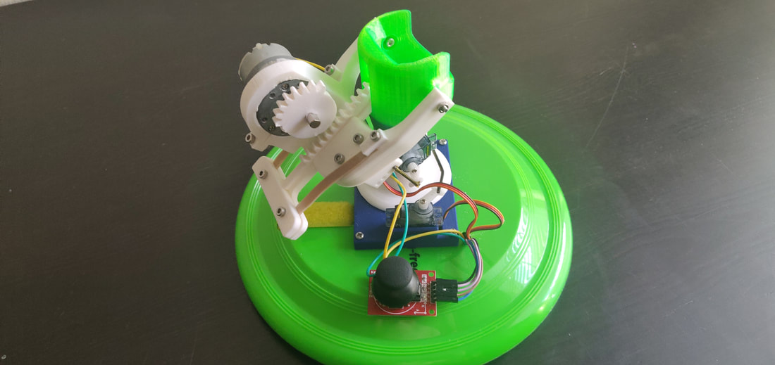
Pictured above is the completed Ping Pong Robot that shoots ping pong balls 6-9 feet far. it uses 2 servos and a single 60 rpm motor to set the direction and fire the ping pong ball. The control system consists of a single 12 volt battery attached to an Arduino Nano and some other components on a printed circuit board.
Below is a video overview and how I went about building a ping pong shooting robot that can shoot a ping pong ball about the length of the table.
Below is the link to all of the CAD and Arduino files for the ping pong shooter and all of my other designs can be found at the following link:
https://www.thingiverse.com/TjomBucket/designs
The necessary components to complete the build:
- M3 nuts and bolts of various sizes (a kit from amazon works)
- Arduino Nano
- Breadboard with jumpers (if you do not plan on getting the board printed)
- L293D motor controller IC - https://www.elprocus.com/h-bridge-motor-control-circuit-using-l293d-ic/
- 5V regulator module - https://www.amazon.com/MCIGICM-voltage-regulator-Regulator-Positive/dp/B07BDFMQF6/ref=sr_1_3?keywords=5v+regulator&qid=1567436795&s=gateway&sr=8-3
- 12 volt battery to power the system ( I used a 610 MaH 3 cell lipo but any 12 volt battery works)
- Nextrox Mini 12V DC 60 RPM High Torque Gear Box Electric Motor (easily found on amazon)
- wires to connect motor to breadboard or circuit board
-2 9 gram servos with coat hangers for push rods - Frisbee (free ones are the best!)
Process for Construction (of the Circuit Board):
- Either get the plans for the PCB sent to a printing company (I used JLC PCB - https://jlcpcb.com/e?gclid=CjwKCAjw-7LrBRB6EiwAhh1yX0-VeAIf8uVehoGngHv0vrYUUpHG6BIlURoMoCaj3TOmisSQEFZE9xoCXn4QAvD_BwE ) or put all of the components on a breadboard
- Gather all of the components
- follow the diagram listed below for wiring
Process for Construction (of the shooter):
- Clean up all 3d printed components. Remove the support material and clean out all of the holes
- Center both of at attach the servo horns to the servos.
- Place the servos into their final locations
- Put the "Middle" part onto the base and put in the "Screw"
- Attach the base to the Frisbee using 4 M3 bolts (you will need to drill out the holes into the frisbee)
- Attach the gear to the motor, then the motor into the "Angle Arm" and add an M3 bolt to tighten the printed part around the motor
- Attach the "Rubber Band Holder Angle Piece" onto the angle arm with M3 bolts
- Be sure to cut about a 1.5-2 inch long piece of rubber band (X2) to put under the "Rubber Band Holder Angle Piece"
- Put the "Rack Gear" into the "Angle Arm" as shown above
- Put the two rubber bands from the "Angle Arm" under the "Rubber Band Holder" part that attaches to "Rack Gear" with 2 bolts.
- Tighten down the clamp on the rack gear with the rubber bands between the two parts
- Connect the Angle arm to the base using the 2 bolts through the side walls of the "Middle"
- Connect the two servos up to the wired electronics board
Personal Takeaways from this Project:
- The Ping Pong Robot was filled with firsts for me. It was the first time I used gears in one of my designs. Usually I would stick to direct drive servo motors because of the ease of application and no need to make center to center measurements as accurate. This time I decided to use gears to allow for a self reloading spring shooting mechanism that was not present in the previous version. This allowed for quick reloads and general ease of use by friends who wanted to play with it. This robot was also the first time I had ever
