-INTRODUCTION:This project is how to make your own brushless speed controller (brushless esc) using H bridges
-PLAN: Brushed speed controllers are cool but very easy as all you need to run them is an input voltage. Brushless motors use variable timing of the magnets to create the rotation, much like a maglev trains use variable timing to move forward. I always use brushless speed controllers in my Rc planes and I was curious to see how they can be made and how hard they are to make.
-PARTS LIST:
-1 Arduino uno (although any would work, you can find this on amazon). The arduino is the main control board for this project.
-at least 3 (you can get more to increase your max working power) L293D H bridges. These chips are used to control the motor.
-1 breadboard (at least 30 by 10). The breadboard is used to mount all of the components for use.
-50 breadboard wires which are used to connect all of the chips together and to the arduino.
- a 12V battery (I used a 11.1v 3 cell lipoly battery pack. you can also use batteries that have a higher voltage like 24 or 36 volts, as long as its under the current and volt limit when running). This battery is used to power the motor.
- 1 potentiometer (10k) which is used to control the speed of the motor.
-1 brushless motor ( any small motor would work, i used this one http://www.amazon.com/Emax-Cf2822-Brushless-Multicopter-Quadcopter/dp/B00DU4A84G/ref=sr_1_18?ie=UTF8&qid=1465184656&sr=8-18&keywords=brushless+emax+motor). This is the motor we will be controlling with this setup.
DESIGN AND MATH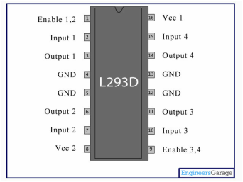
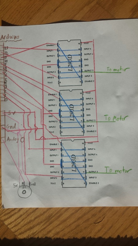
This project uses 3 of these L293D H bridges that usually are used to control brushed motors. The L293D has 2 sides which are separate from the other. Each side has a maximum working current of 600 mah and a max burst of 1.5 ah, but i connected both sides together (as seen in the picture at the top) to increase my maximum working amperage. To get total power you use the equation volts X amps= watts. so far we have 1.2 as the amps so with every volt increase we get a direct correlation with the more watts available for the motor. The chips are rated up to 40 volts which means I could go all the way up to 48 watts (not a lot of power, the wall socket gives 2400 watts). sadly the motor we are using is only rated to 12 volts so we will be using a 12 volt lipoly battery giving us only 14.4 watts to work with, so do not expect massive torque from this motor.
Having more power is good but without being able to time the power it has no use. The arduino is used to make a PWM (pulse width modulation) signal that varies the ENABLE pin on the L293D chip when to turn on and at what power to turn on at. This is what allows me to time each pulse and its power in order to make the motor turn at different speeds. |
PROCESS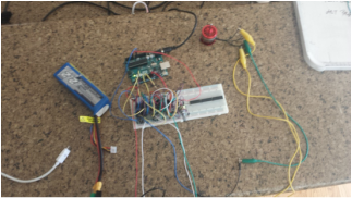
1.To begin this build get all of your parts together so that you can build fast and easily
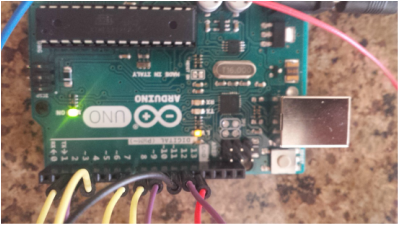
2. take your bread board and place the three l293d chips on the board with pin 1 closest to you 3. wire both sides of the chip together like seen above in blue 4. wire the wires to the arduino in their designated pins. this is in red. 5. take the output number 2 ( or the one connected to output 2) from each of the chips and there are your 3 wires that you connect to the motor in any order (if you switch 2 of them the rotation will change). this is in green 6. wire up the potentiometer. this is colored pink in the diagram Remember: always check your wiring before you turn it on so that you do not burn out any of the components! |
Overall ThoughtsThis project was a lot of fun, I was able to learn about what makes this special type of motor turn. I was able have speed control by using the potentiometer, but that only gave me about 20% of its true speed to work with. This is because of the low amperage that I can pull with this setup. There is so little torque that if the speed gets lowered to much it stalls. The only difficulty i had was making getting the motor to spin up at the right speed. If it sped up to fast it would stall and if the motor goes to slow it wont start. The one thing that i wish i added was reverse and more of the l293D chips. with the 3 chips connected together i was only allowed to pull 1.2 amps without hurting the chips. I was pulling 1.7 amps which is more than what the chips were rated for making them hot. There is a video below showing the motor running and the amp meter plugged in. Overall, this was a fun project that i will definitely revisit and put to use somewhere in my life.
|
The Brushless Speed Controller in Action
Here is a video of the working final product. As you can see it is able to start on its own and then from there i am able to use the potentiometer to move around the rpm by small amounts.
Reading Current Draw
This video shows what the current is when the motor is running during start up and at full speed. The maximum amperage occurs at start up which is 1.73 amps which is under the burst current so that is OK as long as it does not last. The problem that i talked about earlier is that it continuously pulls around 1.70 amps which is over the maximum current and not good for the chips.
